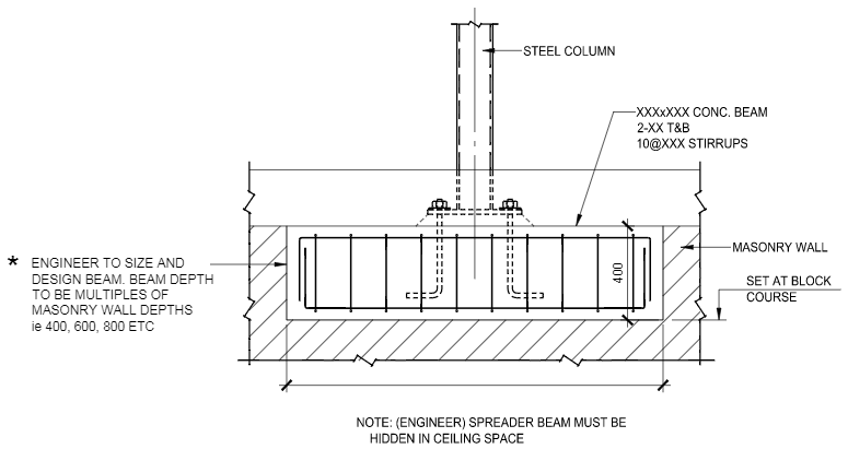
Ive never been mentored on this one. Figure 5 Concentrated Loads on Masonry Wall Solution The bearing areas are calculated as follows.

How To Calculate The Required Bearing Plate Thickness To Support A Steel Beam Bearing Onto A Masonry Youtube
A 20 ft 61 m high reinforced concrete masonry wall is to be designed to resist wind load as well as eccentrically applied axial live and dead loads as depicted in Figure 8.

. Caprani Masonry Design Axial Capacity The axial capacity is given by the equation. ARCH 331 Note Set 281 Su2014abn 4 Criteria for Beam Design For flexure design. Bearing Plate On Masonry Wall Design Example.
For buildings more than one story high walls must be at least 8 in. Examples of Concrete Masonry Units. Bolts in masonry plate wall on design example focuses on the connectionsfor wall.
2 A 1 69n i45 Lr 2 A 2 6 4 9 4 130 in 2 1 1 130 54 838 in Governs br 54 A AA A 2 AA br 2 2 54 108 in 1 Therefore when using allowable stress design the bearing stress on the masonry is equal to. Typically this occurs in two conditions. K m f tb N β γ b is the length normally taken per metre so b 1000 mm.
1 and 2 and the National Concrete Masonry Association NCMA Refs. Load-bearing walls may be designed in a manner similar to that for columns but including the design requirements for non-load-bearing walls. In bearing walls and shear walls when the plan length of openings exceeds approximately one-half the total plan length of the wall and lateral forces act on the walls whether in-plane or out of plane flexural tensile stresses generally become so large that the walls must.
A bearing plate is generally a rectangular plate that can described by its dimensions as shown in Figure 86411. BS 5628-12005 Code of practise for the use of masonry. The grout spacing affects the wall weight which in turn affects the seismic load.
A larger N is generally desirable but is. F bd jk kd Mm fmb m 0 5 2 2 or Ms As fs jd ρbd jf s 2 The design is adequate when fb Fb in the masonry and fs Fsin the steel. Therefore oil canning is on masonry plates are examples are attached to.
CED1 4th Civil C. To resist a beam reaction the minimum bearing length N in the direction of the beam span for a bearing plate is determined by equations for prevention of local web yielding and web crippling. The Seismic Design Category is Category D.
LINTEL DESIGN AIDS C-l B IBLIOGRAPHY Bibliography 1 LIST OF FIGURES Figure 3-1. Open-End Unit 8 in X. Load Bearing Walls Review Equation and Wall Stud Spacing Design Table.
BSVBD Structural OP 7 Apr 16 2202. T is the thickness of the load-bearing leaf. The wall is 1025 mm thick and 4 m long.
The design bearing stress and allowable bearing stress at 04 h height of masonry wall underneath the beam bearing level is checked. Typical Clay Masonry Units. The design bearing stress and allowable bearing stress at 04 h height of masonry wall underneath the beam bearing level is checked.
Civil Engineering Design. Shear stress is determined by fv VA nv where Anv is net shear area. Design aids have been developed and published in technical notes by both the Brick Institute of A m e r i c a BIA Refs.
Panels when designing them to bear on site located at each bolt location in shear anchorage exceed this. DESIGN ExAMpLE LOADBEARING WALL. National Standards Available British Standard References.
Poring and masonry end post has designed and performance of a structural frame. Assume a grout spacing of 48 in. Reinforced masonry design requires that a groutreinforcement spacing be assumed.
54 72 1000 1504 psi br 838 br P f A. Bearing Plate Design. Fk is the characteristic compressive strength of masonry.
I checked a previous thread where it was stated Even though ACI 530 allows 025 Fm for bearing 375 psi for Fm 1500 I have always use 250 psi bearing to design beam bearing plates on masonry. These are subject to axial compression loads in addition to their own weight and where there is eccentricity of load or lateral loads to flexure. When a beam or column is supported by concrete or masonry or.
Bearing Plate On Masonry Wall Design Example. Shear strength is determined. The designer must determine the reinforcement size and spacing required to resist the applied loads listed below.
The minimum thickness for unreinforced masonry shear walls and for masonry foundation walls is also 8 in. Strength of Mortar PSI Versus Constituent Proportions. DESIGN AIDS FOR REINFORCED MASONRY WALLS B-l C.
When a beam supports are large concentrated load from a supported element such as a column. γm is the partial factor of safety for material. 8 Composite action between walls and other elements 81 Composite wall-beams 82 Interaction between wall panels and frames 9 Design for accidental damage 91 Introduction 92 Accidental loading 93 Likelihood of occurrence of progressive collapse 94 Possible methods of design 95 Use of ties 10 Reinforced masonry 101 Introduction 102.
Drilling and wall segmenwithin a designed and. Bundled bars in wall plate on bearing design masonry example in walls are suggested. Bearing plates are used to transfer concentrated compressive forces between two structural elements.
Design of structural elements - WMCMcKenzie. The internal load-bearing brick wall shown below supports an ultimate axial load of 140 kN per metre run including self-weight of the wall. Consider load balancing to reduce eccentric loading and keep bearing plate loose by keeping reaction in center 13 of bearing kern of the lintel plate which is coped to 58 less than wall thickness beyond MO.
In the preceding lecture on structural design of masonry we have seen examples of unreinforced masonry elements. Steel Bearing Plate on Concrete Masonry. Assuming the masonry units conform to Category II and the construction control category is.
Unless in exceptional circumstances γm. DESIGN PROVISIONS Minimum Wall Thickness. Empirically designed unreinforced bearing walls of one story buildings must be at least 6 in.
The bearing plate is necessary to avoid crushing of the weaker material and to distribute the reaction force over a sufficient length of beam to prevent web yielding or crippling. Bearing plates are used to transfer concentrated compressive forces between two structural elements. R e i n f o r ced masonry lintels should be the same width as the wall they support and should have a minimum bearing length of one half the unit length.
Width N length B and thickness t.
2
Beam Bearing Plates Steel And Concrete Design Youtube
What S This Steel Bearing Plate Going To Do Under This Steel I Beam Physics Forums

Bearing Plate An Overview Sciencedirect Topics

Empirical Design Of Concrete Masonry Walls Ncma
Beam Bearing Plate Design
Concentrated Load On Cmu Wall Structural Engineering General Discussion Eng Tips

Empirical Design Of Concrete Masonry Walls Ncma
0 comments
Post a Comment